Title: Bimetallic-MOF Derived Carbon with Single Pt Anchored C4 Atomic Group Constructing Super Fuel Cell with Ultrahigh Power Density And Self-Change Ability

Recently, Professor Junqing Pan Group at college of chemistry published a research paper entitled “Bimetallic-MOF Derived Carbon with Single Pt Anchored C4 Atomic Group Constructing Super Fuel Cell with Ultrahigh Power Density And Self-Change Ability” in Advanced Materials (Adv. Mater. 2023, 2308989).
The development of high-power fuel cells (FCs) is an important strategy to achieve the carbon neutrality target. The sluggish kinetics of oxygen reduction reaction (ORR) greatly limits the improvement of the output power of FCs. Onboard FCs require 5-7 times higher transient power than driving vehicles for accelerating and climbing scenes, which intensifies the demand for output power. Existing electric vehicle manufacturers use fuel cell stacks with excess redundant power (up to 500%) to meet the requirement of transient power, significantly increasing the cost of noble metal catalysts and manufacture. Therefore, it is very important to develop ultra-high-power FCs, which not only requires the exploitation of high-performance ORR catalysts, but also breaks through the function and mechanisms of FC from single energy conversion function to multiple functions of energy conversion, storage, and release.FCs have a gas-liquid-solid three-phase interface for ORR and supercapacitors (SCs) have an electric double-layer capacitance (EDLC) structure. How to use this composite electrode structure to construct a fast discharge mechanism with “ORR+EDLC” parallel discharge between the interface of carbon carrier and the electrolyte is an important strategy to solve the problem of the low transient power density of oxygen electrode caused by the sluggish ORR kinetic process under heavy discharge load. The new fuel cell with supercapacitive co-discharge capability is expected to significantly reduce the load amount of noble catalyst and the cost of existing FCs, which will be an important strategy for commercializing EVs.

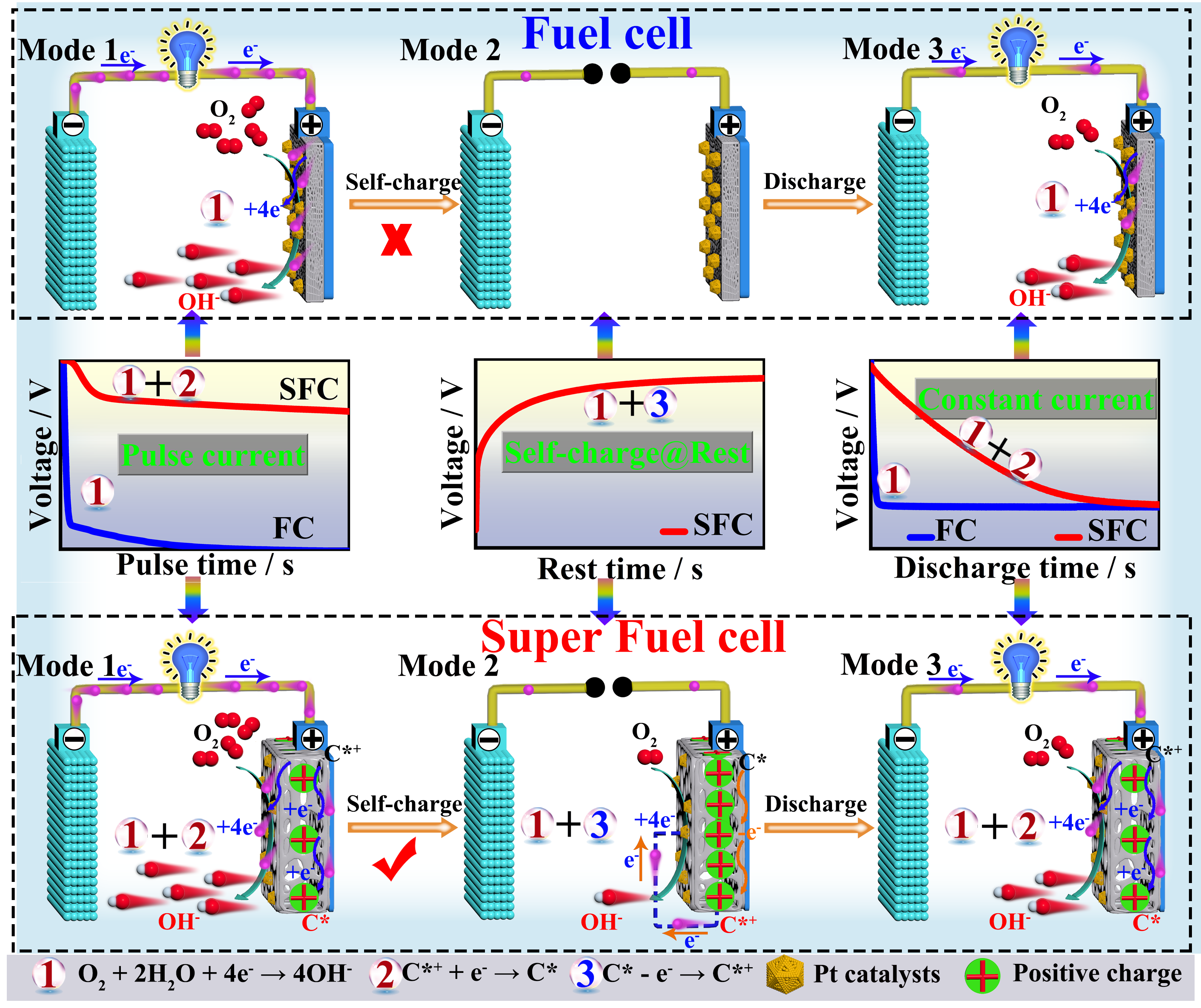
Fig. 1. Schematic diagram of a conventional fuel cell based on 20% Pt as air cathode and a super fuel cell based on PtSA-1.74/HPCNR as air cathode with “ORR+EDLC” parallel discharge and self-charge ability under different discharge scenes.
In this work, we take a unique approach and propose a novel mechanism of “ORR+EDLC” parallel discharge to construct a new super fuel cell (SFC) with fast energy conversion, storage, and release, and the corresponding catalyst material of single atom platinum anchored on hollow porous carbon nanorods derived from bimetallic InZn-MOF (PtSA-m/HPCNR).Fig. 1 shows the working principle and the discharge profile under different scenes of the SFC system. For the pulse current discharge process (Mode 1), the PtSA-1.74/HPCNR catalyst undergoes the ORR process of O2 molecules by the reaction (1), and positively charged carbocations (C*+) obtain electrons to realize the discharge process of EDLC by the reaction (2). The EDLC effectively eliminates the high polarization problem caused by the hysteresis effect of O2-diffusion during high-current discharge, providing several-time higher discharge voltages than existing FCs. For the self-charge ability of SFC (Mode 2), the driving force for self-charging comes from the difference between the actual electrode potential and the theoretical potential of the oxygen electrode. When the oxygen electrode is at rest or discharging with a low current, the diffusion rate of oxygen is greater than that of oxygen consumption by the oxygen electrode, causing the surrounding oxygen concentration to gradually increase. At this time, the Pt SAs micro-positive electrode charges the carbon micro-negative electrode on the HPCNR, and when the electrode potential is close to the equilibrium potential of oxygen, the charging current (I) tends to 0 until self-charging stops as the ΔU between the Pt SAs micro-cathode and the HPCNR carbon micro-anode decreases.
To achieve the SFC with high “ORR+EDLC” parallel discharge properties, it is essential to exploit uniform hollow porous carbon nanorods (HPCNR) as carriers of Pt SAs with an open structure to facilitate the efficient ORR process. This unique PtSA/HPCNR composite was prepared by carbonization, acid washing, and rapid reduction processes of InxZny-MIL-68 as a precursor to form bimetallic InxZny-MIL-68 hexagonal prisms (Fig. 2).

Fig. 2. (a) Schematic illustration of the synthetic route for Pt SAs immobilized on high-capacity bimetallic MOF-derived hollow porous carbon nanorod (PtSA-m/HPCNR) composites. TEM, the corresponding HR-TEM images and SAED patterns of (b) In1Zn2-HCNR-4, (c) HPCNR-4, and (d) PtSA-1.74/HPCNR materials. (e) HAADF-STEM image, (f) AC-HAADF-STEM image, and (g) the magnified image of PtSA-1.74/HPCNR material. (h) EDX spectrum and (i) the corresponding EDX elemental mapping images of Pt SA-1.74/HPCNR material.
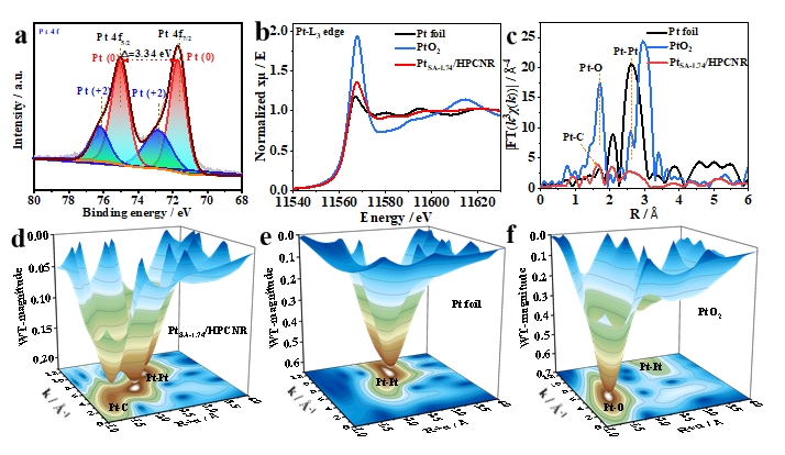
Aberration-corrected high-angle annular dark-field scanning transmission electron microscope (Fig. 2), X-ray absorption fine structure (Fig. 3), and density functional theory calculations (Fig. 4) demonstrate that the synergistic effect of Pt single-atoms anchored on carbon defects significantly boosts its electron transfer, ORR catalytic activity, durability, and rate performance.

Fig. 3. Electronic states of atoms in PtSA-1.74/HPCNR catalyst. (a) High-resolution Pt 4f XPS spectrum of PtSA-1.74/HPCNR. (b) XANES spectra and (c) FT-EXAFS spectra of k3-weighted Pt L3-edge for Pt foil, PtO2, and PtSA-1.74/HPCNR. k3-weighted Pt L3-edge WT-EXAFS contour plots of (d) PtSA-1.74/HPCNR, (e) Pt foil, and (f) PtO2.

Fig. 4. (a) Optimized structures and (b) Charge density difference of Pt-C2/G, Pt-C3/G, and Pt-C4/G. The yellow zone indicates a gain of charge and the blue zone a loss of charge. (c) The combined projected density of states (PDOS) of pristine G, Pt-C2/G, Pt-C3/G, and Pt-C4/G. (d) The adsorption-free energy (△Gads) of different ORR intermediates OOH*, O*, and OH* on Pt-C2/G, Pt-C3/G, and Pt-C4/G. Free energy diagrams of different ORR intermediates OOH*, O*, and OH* for Pt-C2/G, Pt-C3/G, and Pt-C4/G at (e) 0 V and 1.23 V, as well as (f) 0.84 V.
